Defining Model Types in Visio
Defining model types involves the following steps:
- 1. Decide on the EVA Netmodeler node and relationship types that you want to represent in your model type
- 2. Create a stencil for the model type by defining a master shape for each node type and each relationship type in the model type.
- 3. Draw a diagram of the model type and save this model type to EVA Netmodeler
Decide on Node and Relationship types
The node and relationship types that you use in your model must already be defined in the EVA Netmodeler repository. Refer to the Modeler Help section for information on how to do this.
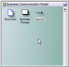
In this example we will work with the following model:

Create a stencil (making new icons and icon masters)
Each shape in the stencil must all have a master icon associated with it. It is essential that the master properties be
set up correctly for each master that is created. This can be done by using stencils provided in Visio, creating custom stencils or a combination of both.
- To open an existing stencil, choose: File, Stencils, Open Stencil.
- To create a custom stencil, choose File, Shapes, New Stencil. A new stencil pane is created and is automatically put into Edit mode. Custom icons for the stencil are selected by left clicking on the stencil title bar
and selecting Find Shape…
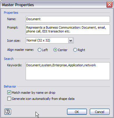
- To create a new master, right click on the stencil bar and choose Edit. This will put the stencil in edit mode. Right click on the stencil window and choose New Master. Create a new master name, check the "Match
master by name on drop" check box and click OK. This ensures that diagram shapes created from the master remain associated with the master so that subsequent changes to the master will be propagated to the shapes
based on it.
- Give the master a name of your own choosing. The name need not be exactly the same as the name of the associated node type in EVA Netmodeler - you will create a mapping from the master's name to the EVA Netmodeler
node type name in a later step.
Formatting the master
- In edit mode right click on the icon in your stencil window and choose edit master. A new window will open. Paste a shape or picture for your master icon.
- To choose the format and positioning of the text for the icons, choose the "Text tool" button, and choose the font, size, etc.
- To reshape and move the text box, choose the "Text box tool".
- When you are happy with the appearance of the icon, close the window and answer yes to update.
- Make sure you save the stencil.

Define the Model Type on the Visio drawing canvas.
To define the model type
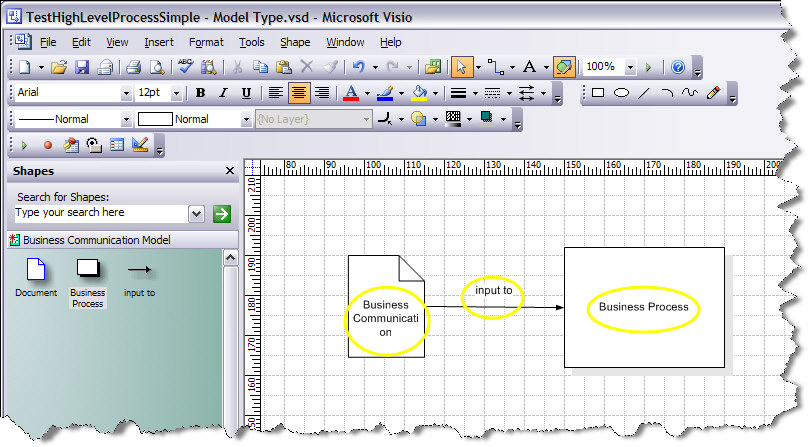
- Place and connect the master shapes representing the node and relationship types on the drawing.
- Label the shapes with the names of the corresponding node or relationship types in EVA Netmodeler. Be sure to use the exact same spacing and capitalization to ensure that the Visio and EVA Netmodeler elements get
correctly matched during the save process.
In the example below, the Visio master shape called Document will be mapped to the EVA Netmodeler node type Business Communication, and the Visio master shape called Business Process will be mapped to the EVA Netmodeler
node type of the same name.

Save the Model Type
Save the Model Type to EVA Netmodeler
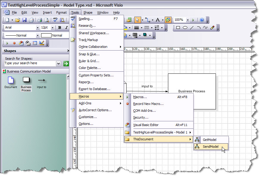
Select Tools \ Macros \ This Document \ SendModel from the Visio menu bar.
Saving a new model type is a three step process, all performed from the SendModel dialog:
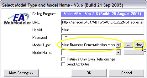
Step 1: Create a New model type. Type the name of your new model type in the Model type text box. Select the New
button on the right of the dialog. This creates an entry for the new model type in the list of model types in EVA Netmodeler
. Wait until the mouse pointer returns from the "wait" state to the "ready" state (hourglass to pointer on most systems)
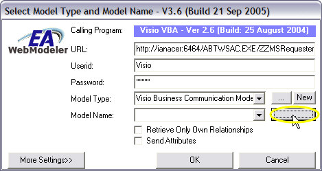
Step 2: Retrieve the list of available models by selecting the "...." button next to the Model Name: text box as demonstrated below.
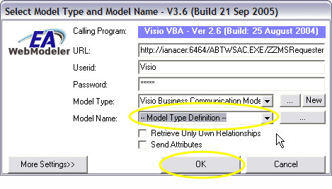
Step 3: Select the "--Model Type Definition--" item from the Model Name list box. Then select the OK button to save the model type definition to EVA Netmodeler
.
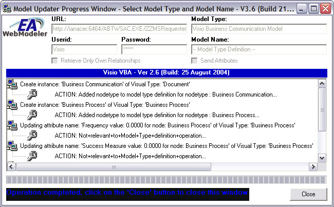
You will see an output dialog similar to the one shown below if you have named the shapes correctly on the model type
diagram, and the model type diagram matches the meta model definition in EVA Netmodeler.
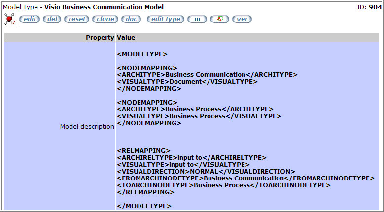
If you like you can verify the result of the save operation by viewing the Model Type definition using one of the EVA Netmodeler
browsers. Shown below is the result of the steps described above. Refer to the Developer section for more information about the model XML structure.
Save the Visio Stencil and / or template
To save the stencil, right click on the stencil title bar and select Save as ... You can then use the stencil to create new models based on the master shaped in the stencil.
To save the new model type as a document template,
- First, delete the model type diagram from the diagram sheet.
- Next, Save the document as a Visio template (.vst), or as a normal Visio diagram
The template or diagram file now contains both the stencil for the model type and the macro code required to send and get models to and from EVA Netmodeler.
You can also save the model type template in the EVA Netmodeler repository. You can do this by uploading it to the "External Tools Template" property of the appropriate Model Type in EVA Netmodeler. This keeps the Model Type
definition and the corresponding Visio diagram template in the same place for easy reference.

More advanced model types and model features
The following more advanced model features can be defined by capturing the required definition directly into the model definition XML. Refer to the section on Model XML for details of the XML structures and usage.
- A single EVA Netmodeler type can be mapped to more than one visual types, based either on a property value or a relationship to another item. This feature is useful when you want the shapes on the diagram to be drawn
differently based on the contents of the repository at the time when the diagram is drawn. For example, you may want a "Manual" business process to be represented by one type of symbol, and an "Assisted" business
process by another, but still have both kinds of business process stored in the repository as Business Processes

Troubleshooting
The most common problems with creating new model types using Visio are:
- The Save process reports that a node type was not found in EVA Netmodeler. This is usually caused by
- The corresponding shape has not been labeled correctly on the model type diagram. Check the spelling, spacing and capitalization of the label. Remember that it is the label that must match the EVA Netmodeler
node type, not the shape name.
- Relationship names not found in EVA Netmodeler.
- Relationships are bi-directional in EVA Netmodeler i.e. they are labeled in both directions. The relationship defined in Visio is only labeled in one direction. This is not a problem as long as you ensure that you draw
the relationship starting from the source node type to the target node type. If you draw the relationship line the other way around you will be telling EVA Netmodeler to record a different type of relationship which
probably has not been defined in the meta model and will therefore cause an error. For example, the relationship "Business Communication --input to-- Business Process" has "Business Communication" as
the source node and "Business Process" as the target node. Drawing the relationship line from "Business Process" to "Business Communication" would be saying that the "Business Process --input to-- Business
Communication", which is not the same thing at all and therefore should and does result in an error.
TIP: To validate the direction of a relationship line in Visio, right click on the line and select Change
Arrowhead from the context menu. Set the line Begin style to something a different to the End style. Now when you draw the line on a diagram you will be able to see which is the start of the line and which is the
end. After verifying that the line has been correctly defined you can set the line begin and end styles back to what they were before.
- Model Type does not appear in EVA Netmodeler after it has been saved from Visio. The most common causes of this are
- Forgetting to select the New button when creating a new Model Type, or
- Forgetting to specify the "--Model Type Definition--" in the model name text box in the Visio SendModel dialog.

|